Sharon
Liu
Habitat's Airlock Linkage System
GoSolo: Self-Assisted Belay Device
Engineering Design II, Fall 2021
For my Engineering Design II senior capstone design project, I worked in a team of 6 to build GoSolo, a product that augments a commercial assisted-braking belay device (the Petzl GriGri) to prevent dangerous falls for solo rope climbers by improving the design functionality of belay braking mechanisms as an effective self-rescue method. The device is meant to be used in a traditional lead-climbing scenario. The current problems within mass market belay mechanisms include the lack of a foolproof method for solo climbers to catch their fall safely and the difficulty of climbing across a terrain using existing braking devices while carrying extra bulk and weight in looping ropes. These also necessitate frequent management on the part of the climber which can significantly reduce performance during a climb. Some of the most reliable soloing devices have been discontinued as well, making them very difficult and expensive to buy. Our main stakeholders are solo rock climbers identified through researching the target market of belay devices. People in this group purchase their equipment from popular belay device companies, such as Petzl.

GoSolo is designed to brake a falling climber without close supervision on part of the climber. It is a ground-anchored device that requires little to no interference while on the climb, which removes excess time needed to stop to feed the rope as the climber ascends. The main mechanical component of this device is a centrifugal clutch that expands and then triggers the GriGri to break the climber’s fall when it hits the set activation speed. Over the course of the semester, we conducted customer and market research, designed working prototypes, and performed evaluative testing in order to improve the functionality of our product.
Design
Overall, the product functions as a belaying mechanism for solo rock climbers. The device feeds rope to a climber during normal ascension along the pulley, and brakes the rope to prevent movement when falling. The device is intended to anchor at a point on the wall or the ground, with the climber above the device. The climbing system encompasses the proposed mechanism, as well as the climber, rope, and anchor. The rope within the system can be subdivided into active and free strands, where the active strand connects the device and the climber, and the free strand is the excess rope below the belay device. The belay system functions by allowing free rope to pass through the mechanism and add to the active rope length if the speed is below a speed indicative of a falling climber, and braking the active strand during normal operation.

The free strand initially contacts the device via a pulley axially mounted on a centrifugal clutch. The rotational speed of the pulley and the centrifugal clutch are equal, and proportional to the speed at which the rope is pulled. After wrapping around the pulley, the rope enters a mass-market assisted braking device called a GriGri. The GriGri uses a friction-triggered camming mechanism to brake the active strand without substantial braking force on the free strand. Our device initially constrains the vertical movement of the cam to prevent activation of the GriGri. The rope passes through the GriGri, which is directly attached to the anchor, and extends up to the climber.
GriGri CAD model with custom centrifugal clutch, with material as steel AISI 1020
The device brakes the rope by using a centrifugal clutch to activate upon reaching a sufficient rope speed. When the shoes of the centrifugal clutch expand at the rope speed indicative of a falling climber (roughly 4.5 m/s), the shoes impact a hinged switch mounted tangentially to the clutch. The switch rotates around the hinge and into a cutout on the clutch, thus abruptly braking the pulley. Simultaneously, the rotation of the hinged switch rotates a pinion gear on a rack. The movement of the rack pushes the component that is restricting the activation of the cam on the GriGri, thus allowing the GriGri to activate if braking force is applied on the free strand.

Exploded view of GoSolo displaying components used for design and manufacturing
The initial pulley holding the free strand of the rope prior to entering the GriGri brakes when the hinged switch enters the cutout segments on the circumferential edge, applying substantial braking force to the rope. In turn, the GriGri camming mechanism activates and the active strand of the rope brakes, stopping the falling climber.
System Function Analysis and FEA on Major Components
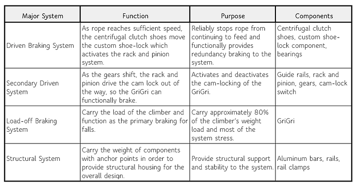
Major systems and their functions in GoSolo device
Component: Clutch Stopper Switch

Clutch stopper switch stress analysis and displacement results for a force distribution of 200 lb load


Damage and fatigue results for clutch stopper switch under estimated max loading

Life cycles that clutch stopper switch is able to sustain under maximum loading criteria
We made the following assumptions for the material properties and load distribution on the clutch stopper switch:
-
Uniform and isotropic material
-
Fixed at connection
-
Load of falling climber directed to switch
-
Reaction force of inner face negligible to falling weight
The loading we tested in this analysis was as if a force equivalent to the entire weight of the climber and equipment (estimated at 200 lbs) impacted the switch when the lock was activated. This is not a situation we expect - the rope is aligned through the GriGri such that the load of the climber is held by its strength. The impact on the switch at the moment of locking is negligible compared to this weight (the momentum of the clutch and the friction on the rope). This FEA was primarily testing for the strength of the switch itself when withstanding free fall of a 200lb load, these results seem to show that our design and material choice was sturdy enough for the mass manufactured product. In the final product, the loading is expected to be offset to the GriGri such that the switch itself would at best withstand 5-10% of that loading. That being said, the FEA shows that utilizing the current clutch switch design will suffice.
Component: Cam lock


Cam lock stress analysis and displacement results for a force distribution of 200 lb load
We made the following assumptions for the material properties and load distribution on the cam lock:
-
Spring attached at the tip of the component is negligible
-
Isotropic material properties
-
Force from GriGri applied uniformly normal to a rectangular approximation of the contact area between the two components
The purpose of the cam lock component is to replicate a belaying partner’s thumb in holding down the cam of the GriGri until a fall. The maximum load from the GriGri onto the cam lock would be equivalent to the amount of force exerted by the partner’s grip (in equivalent situations based on Newton’s Second Law). In setting the parameters for the FEA simulation, we treated the face of the hole about which the part rotates as fixed. We applied a load at the interface between the cam lock and the cam (simplifying it to a rectangular area) of 545N, equivalent to a measurement of peak grip force. The deformation of the component was the most important point of analysis because if it deformed under loading to the degree that the GriGri cam was able to fully activate, then it would not be fulfilling its purpose. In order to evaluate the results of the deformation analysis, we measured the GriGri in both of its states of operation, and observed that at the point of contact between the GriGri and the cam lock, the GriGri displaces by 2.7 cm when activated. Our FEA deformation showed that the displacement of the cam lock (with 0.25” thick acrylic) at this position would be approximately 1.2 cm, less than half of the functional limit, even when performing at the level of a peak-strength human. This supported the idea that our material and dimension choices for this component would be successful in our device, and confirmed the design decision to double the thickness of the acrylic from 0.125” to 0.25”.
Component: Rope speed and spring constant calculation
In order to develop the design requirements for our centrifugal clutch, we set an activation goal of a 1 m fall. Since our device is replacing a person, we wanted to set this requirement based on observed human reaction time and motor response of about 0.4 seconds. A consistent assumption throughout this analysis is free fall (ignoring air resistance). Therefore, through dynamic analysis, we estimated that the system should lock after a 1 meter fall. The activation speed of the clutch is the speed that the rope would be moving after this distance of falling. Assuming free fall with a negligible initial velocity:
As a result of this analysis, we set the target rope activation speed to 4.5 m/s. We used this to determine an initial parameter for the clutch springs’ stiffnesses (which we iterated on through prototype testing and design refinement). Assuming linear elastic expansion springs, and activation when the spring force overcomes the centripetal inertial force:
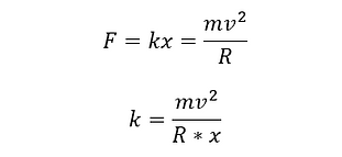
Based on our calculated activation speed (v), the mass and radius of the part, as well as the necessary expansion for the clutch shoes to impact the switch (x), we calculated a spring constant of 50 N/m, or 0.3 lb/in. This was how we chose the springs for the clutch.
Prototype Iterations
Prototype I
For prototype 1, we aimed to test the centrifugal clutch as a method of activating the GriGri. The critical design decisions we were investigating were the reliability of our device’s activation, the optimal transfer of the clutch locking to the GriGri, and the optimal mechanism to lower the brake strand. We needed to determine whether a centrifugal clutch device would allow for the detection of a climber fall, activation of the GriGri, and immediate locking of the rope. A wooden frame served as the base with a mount to hold the GriGri and the components of our device. The centrifugal clutch was located on the same shaft as a rope spool, such that a fast speed of the rope would translate to the activation and expansion of the clutch shoes. When the clutch expands, the shoes impact the bottom of a lever, causing it to swing and release the latch at the top. A pulley on a shaft previously supported by this latch (as well as a parallel lever on the opposite side) falls down a slot in the frame. The rope is passed through the redirection pulley between the GriGri and the spool, so when the system is activated, the rope falls below the plane of the GriGri. This was intended as a braking mechanism similar to what a human belayer would do to ensure activation of the GriGri (pull the brake strand below the GriGri). The following image shows the final version of our prototype 1.
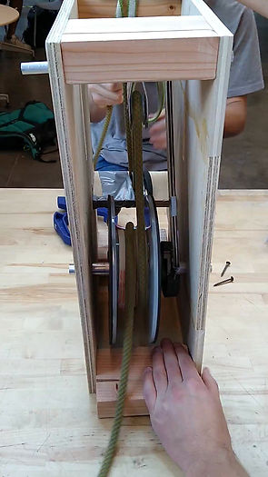

Prototype I testing along with major acting components for braking mechanism
Prototype II
Prototype 2 is shown below. Since this prototype featured a fully custom centrifugal clutch, the components we analyzed were important in deciding the strengths of the newer design. This prototype is deliberately more compact in design as for ergonomics when carried by a climber. Likewise, the parts that were manufactured were designed for mass production. The front and back plates are relatively simple parts that were manufactured using a manual milling machine. The clutch and pulley are combined in one part and were manufactured using a combination of techniques. The pulley groove was manufactured on a lathe while the holes were drilled and tapped on a mill. The slots for the switch were milled using a CNC machine. The switch was also made using CNC due to its complex shape. The two plastic parts, the GriGri holder and cam lock, were manufactured using 3D printing and laser cutting respectively. For prototype 2, we conducted testing by using weights to simulate a falling climber. The goal of these tests was to evaluate our custom-made clutch as well as the overall functionality of the device since the new design was a significant shift from prototype 1.

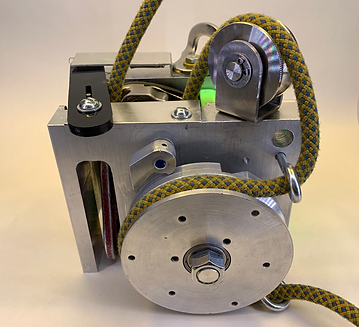
Construction of prototype II along with refined braking mechanism and machined parts
Design Expo Poster
