Sharon
Liu
Habitat's Airlock Linkage System
Electric Scooter Throttle and Brake Subassembly
Engineering Design I, Fall 2020
For my final project, I worked with a partner to modify an existing CAD model of an electric scooter. The subassembly prototype model consists of a throttle and brake subassembly revamped for teenagers with wrist and hand tendonitis. The subassembly is located toward the footing and standing board of the electric scooter model, designed to reflect conventional vehicle maneuver with throttle and brake pedals. It must be able to sufficiently support constant footing loads and made of durable, lightweight material. Since the class went remote during this year, we could not build the prototype or do performance tests. However, we created a working model and performed FEA on the important components. The preliminary scooter model was taken from Grabcad.

Subassembly isometric view with break and throttle pedals, displacement sensor, brake fluid reservoir
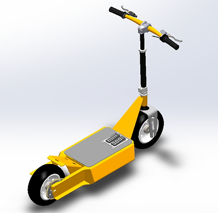
Integrated subassembly with electric scooter model
Concept to Prototype

Our prototype mainly utilizes foot braking and power. The system of brake and throttle pedals relocated at the standing deck of the scooter will reduce the hand effort that teenagers with wrist and hand tendonitis have to use in order to brake or accelerate the scooter, thus increasing their comfort level while riding. The scooter uses hydraulic braking. Applied force by foot compresses the brake piston, pressurizing its affixed fluid through the cable lines. The cables connect to a larger piston on the wheels, which get compressed and stopped. Similarly, force applied to the throttle pedal displaces the throttle piston and activates a position sensor wired to the scooter’s engine control and accelerates the scooter.
Concept sketch and design of major acting parts
The brake pedal can be manufactured from ABS plastic. The stresses on this part are relatively low, so ABS will be able to withstand regular use. This material is also inexpensive in comparison to other possible materials such as steel or aluminum. Injection molding can be used to manufacture the part, and since the product is manufactured on a large scale, the initial capital cost of the molds will not be proportionally significant.
The housing can also be manufactured from ABS. This is the largest part of the new subassembly, so it is preferable to keep it lightweight so that it does not add significantly to the overall weight of the modified product. When conducting inverse analysis for this part, it was found that the required yield stress was 1563 psi which is lower than that of ABS. This means that ABS will be sufficiently strong to support the applied loads while still being much lighter than many other materials.

2d and isometric views of prototype modeled
The throttle and brake pistons can be made from stainless steel. The brake piston will be in contact with hydraulic fluid, so it must be resistant to rusting which is why stainless is preferable to other types of steel or other similar metals. This part can be manufactured using die casting. The geometry is simple and does not have any back-cuts which will allow a mold to easily be formed. Since the product is manufactured on a large scale, the initial capital cost of the mold will not be proportionally significant.
Transmission of power
Vertical force from the foot on the throttle pedal displaces the piston-spring system. The pedal does not rotate or create a moment, but is instead fixed to the piston on the bolted point. Located along the throttle piston is a welded activator metal used to signal the linear position sensor. The activator metal uses induction to trigger the position sensor within the gray strip range through a linear downward motion on the y-axis. This sends a signal to the engine control module (ECM), which revs the motor and accelerates the wheel through a gear train attached to the engine. Cables and electronics are connected to the scooter’s battery, and the wires lay in the battery housing.

Transmission of power for throttle pedal
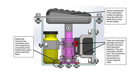
Transmission of power for brake pedal
Vertical force from the foot on the brake pedal displaces the brake piston, which creates an opening in the piston and pressurizes the seeping brake fluid. These small valve openings are attached to brake line cables. This causes the pressurized fluid to travel along the cable to the larger piston attached to the wheel disc and brakes the wheels. The brake fluid reservoir, which houses the pressurized fluid, has a cable to the openings of the piston.
FEA
Since the user population that this modified product supports are teenagers with wrist and hand tendonitis, the predominant location of the force applied by the user would be at the standing deck of the scooter as well as the pedals. There would not be a significant force applied to the grips. The only other forces are reaction and normal forces, along with internal torque by the scooter motor, but are not shown in the FEA as they do not directly affect the subassembly. In the FEA analysis, the loading along the deck uses a worst-case scenario of a distributed force of 220 lbs by the user, as provided in the project description. The distributed load at the bottom of the housing accounts for the force by the foot to the pedals and pistons, and from those reaction forces to the housing.
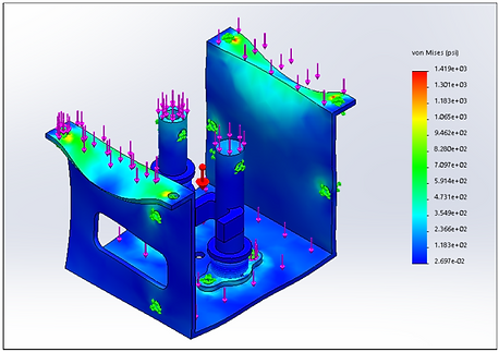
Max stress for pedals onto pistons and housing

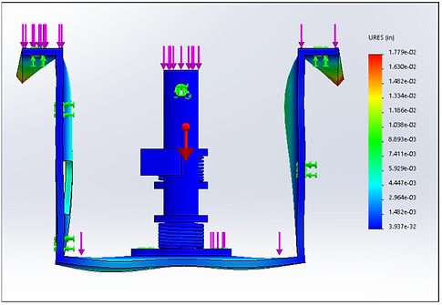
Max displacement for pedals onto pistons and housing

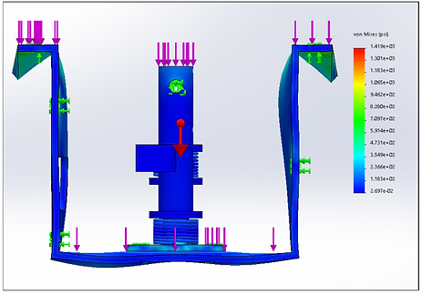
Max stress for brake pedal

Max displacement for brake pedal
The housing holds all of the components in the subassembly. It is mounted at the top to the deck of the scooter, which are represented by fixed points. There is a distributed force along the pedals, representing the compression force from the foot. Underneath the pedals, there is a reaction force from the piston-spring assembly back onto the pedals. The pistons create reaction forces to the inner bottom of the housing by the pedal-piston systems. Additionally, the weight of the subassembly at the center of gravity of the system and the weight of all of the components within act on the inner bottom of the housing. This is the same orientation and loading as for the modified product, just that the piston components are inclusive in the model for the subassembly. This orientation and loading is different for the three components separately since the forces are grouped together, some being internal and consecutive forces, which are not shown in the FEA, whereas the components have all the reaction forces acting on it.
Overall, the FEA aligned with the inverse analysis for FOS and we were able to gauge worst case scenarios for the materials used on each component. We determined that the materials used would sufficiently support the user while providing a cheap, yet lightweight alternative for mass-market manufacturing.
Bill of Materials
