Sharon
Liu
Habitat's Airlock Linkage System
Astronaut's Coat Rack
Engineering Design I, Fall 2020
The objective of this project was to design a laser cut acrylic hanger that could support the load of a weighted astronaut suit in space. The hanger is attached to a rig with certain positional constraints along the pegs. The hanger must also withstand a 40 pound load without breaking, acting effectively as a reusable and space-conversative hanger. I used inverse analysis and Solidworks FEA simulations in order to determine an optimal geometric design under standard acrylic material constraints.
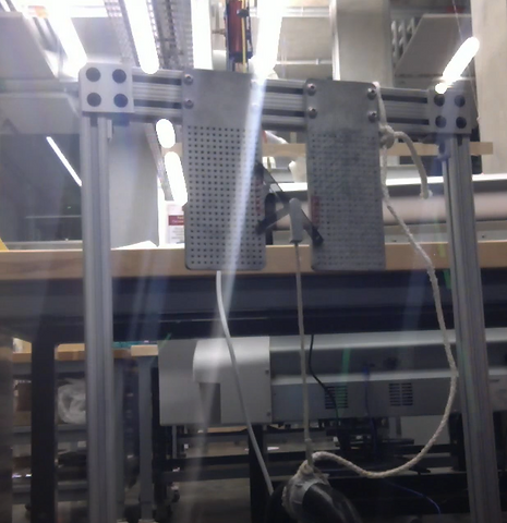
The hanger tested on the physical mounting boards. The hanger is attached with pegs and the weight simulating the astronaut suit attaches to the mounting point on the hanger in the middle.

Side by side comparison
Testing Rig Specifications

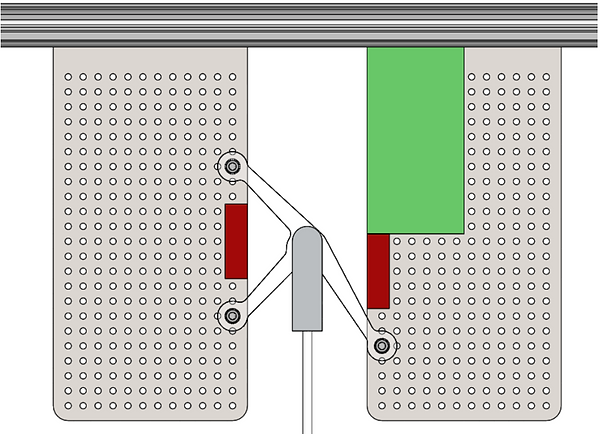
The testing stand has two zones. The hanger is able to overlap the green zone, but not mount anywhere on it. However, the hanger is not allowed to overlap nor mount on the red zones.
The testing rig has two plated mental board stands. The pegs on the board attach to the hanger to keep it upright.

The dimensions and expected range of size for the hanger and zones relative to the mounting boards.
FEA for material strength
In the FEA, the hanger was projected to fail in the center where the suit clip was attached. The hanger weighed 5.97g. The conditions set on the hanger were: the peg legs acted as fixtures (x and y reactional forces) and the center weighed by a 40 lb load. The center showed the region where the max stress and displacement was projected to occur.
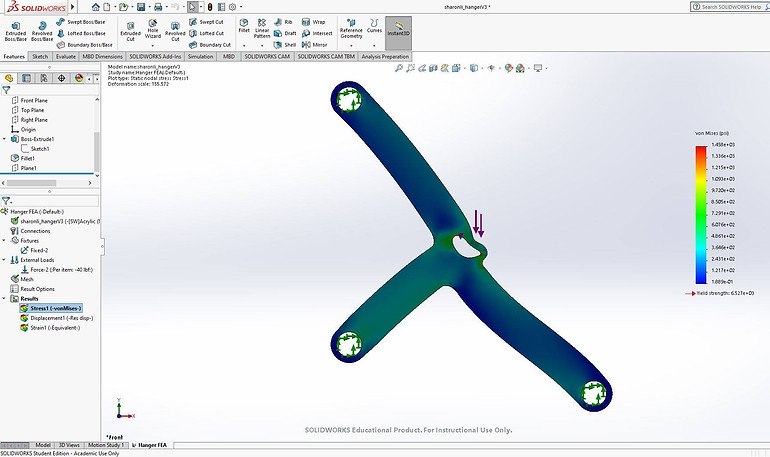
FEA max stress for prototype hanger 1

FEA max displacement for prototype hanger 1

Physical failure at top peg leg and middle
As suggested from the FEA, failure occurred at the middle. However, the top peg had unaccountably failed as well. This was speculated to have been gravitational effects coupled with more tension along that leg relative to the other two.
Improved Iterative Design
The new hanger design focused on sustaining the functionality of the original hanger, but with more supportive material from where failure occurred in the first prototype. FEA and evaluative testing showed that failure was mostly likely to occur at the top peg and center. Hence, material along the legs was reduced, while the areas where the pegs attached were boned out.
Improved hanger design on peg board


Weighing 2.53g, nearly half that of the original design, the new iteration as seen in the FEA, shows less propensity to break in the center where the load attaches. The thicker material surrounding the center is projected to counter the stress concentration from the clip. Likewise, the bone design at the peg holes is projected to counter the reaction forces from the pegs, reducing the likelihood of failure.
Although due to the remote nature of the class, I was unable to evaluate the new iteration with physical testing. This was due to an inability to access the printing lab and also the lack of resources. However, inverse analysis and FOS calculations show that the new prototype design would pass the benchmark testing of withstanding the 40 lb load. The new design is refined to minimize stress concentrations, superposition of forces, and reduce mass for portability.